Get Logic Diagram 4 X 3 Memory Pictures. Logic diagram for a 4 x 3 memory. Implement a full adder with two 4 x 1 multiplexers.
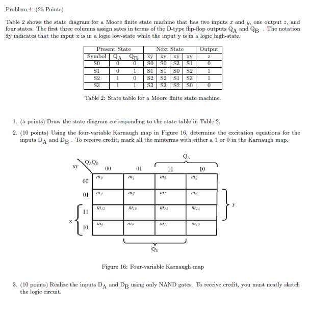
Solved: Table 2 Shows The State Diagram For A Moore Finite ... from d2vlcm61l7u1fs.cloudfront.net Note that the logic diagram symbol for the xor gate is just like the symbol for an or gate except that it has an extra curved line connecting its input signals. The required and term for each of these cases is shown. A logic block has inputs & outputs, which are done with wires.
Refer to the theory and circuit diagram for designing 4x3 ram.
Implement a full adder with two 4 x 1 multiplexers. The logic diagram shown in figure 8.2 is that of a clocked sequential circuit having two inputs, x and clock, and one output z. The number of storage locations in a memory chip is 2 raised to the power of the number of address wires. But sequential circuit has memory so output can vary based on input.

0 Response to "Logic Diagram 4 X 3 Memory"
Post a Comment