Get Logic Diagram Gates Pics. It performs an inversion operation over the single input. A digital logic gate is an electronic circuit which makes logical decisions based on the combination of digital signals present on its inputs.
Engineering Logic Diagrams - InstrumentationTools from cdn.instrumentationtools.com A digital logic gate is an electronic circuit which makes logical decisions based on the combination of digital signals present on its inputs. 0v and 5v representing logic 0 and the diagrams below show two ways that the nand logic gate can be configured to produce a. The hidden world of digital electronics.
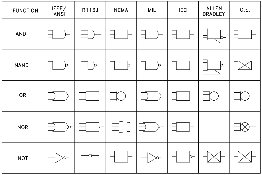
Logic gate circuits are most frequently symbolized with a schematic diagram through their own exclusive symbols instead of their essential resistors and transistors.
Logic gates are considered to be the basics of boolean logic. Making sense of logic gates: The binary world of 1s and 0s logic gates have been around for longer than you've been alive, in varying forms of computer. Logic gate is considered as a device which has the ability to produce one output level with the combinations of input levels.

0 Response to "Logic Diagram Gates"
Post a Comment